General Information
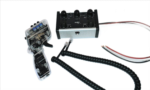
Basic Controller set-up starting point.
Here is a guide for a simple controller with Brake and Sensitivity adjustments.
More complex controllers still basically only have speed and brake adjustments, but will have additional features surrounding those two functions. For these complex controllers, simply turn the extra features to mute their effect until you have this basic set of adjustments understood and mastered.
More complex controllers still basically only have speed and brake adjustments, but will have additional features surrounding those two functions. For these complex controllers, simply turn the extra features to mute their effect until you have this basic set of adjustments understood and mastered.
Sensitivity Adjustment (Analogous with changing the Ohms of your controller)
(For complex controllers simply dial the additional features to have minimum effect)
(For complex controllers simply dial the additional features to have minimum effect)
- Turn the brakes up to maximum
- Turn the Sensitivity down to minimum
- Connect the controller to the rostrum and then place the car onto the track. (Take extra care if you are not using a single 3-way plug)
- Pull the trigger to just connect with the segments of the wiper contacts. (You will see the brake terminal disconnect)
- Hold the trigger in this position and then slowly turn up the sensitivity pot until the car starts to move.
- Let the car travel around the track while you adjust the sensitivity to the point where it will still go around the tightest bend at this slowest setting.
The idea here is to give you the biggest range of trigger sweep to control your car.
If you set the sensitivity too low, then you have to move the trigger further along the range of movement before the car starts.
This reduces the range of movement between the start speed and full speed, so makes the car more difficult to drive.
If you use a passive resistor controller, then you can think of the sensitivity as adjusting the Ohms value of the controller.
________________________________________
Brake Adjustment
- Drive the car at racing speeds and then adjust the brake control to set how fast the car will stop.
Initially you have it set at maximum, so it should just be a case of turning it down to suit the racing conditions.
With some cars, the magnetic effect and the magnets are so strong that they stop very fast, even with no brakes applied.
For these cars, turn the brakes down to the lowest setting.
The MT II and Apex controllers have features that provide Coast Braking adjustments to cater for cars that stop very fast even with no braking applied.
Driving technique and individual style and preference is really the most effective way to determine controller settings, but this guide may help to start off with.
________________________________________
Slot Car Track Plug Wiring
Standard Positive Wiring Example: Wiring image 1
Standard Negative Wiring Example: Negative image 1
Poly Car Wiring: Positive wiring on 3.5mm Jack
Scalextric and Ninco Analogue plug Wiring Example: Negative Wired 3.5mm Jack Plug
UK: Wiring Image 2
________________________________________
General Servicing Instructions
Intermittent controller operation. (Possible home remedies)
Most people keep their controllers clean in the same way they do with the car braids or tyres, but sometimes intermittent issues can arise.
Make sure of the following :
- The trigger wiper fingers and contact board are clean.
- Tension of the wiper fingers against the contact segments on the board are gentle but secure.
(only light tension is needed, but they must remain in good contact) - The trigger loop wire is in good condition.
(If the loop wire is not present please see "Trigger Loop Wire" below) - The trigger saddle is secure.
- Contact between the saddle and the Brake terminals are clean.
- Contact between the saddle and the Max speed terminal are clean.
- The mounting nuts and washers on all boards are all secure.
- Connections from the cable into your plug or hook up terminal are secure.
- The Cable may have an intermittent metal fatigue break, usually at the exit from the handle.
________________________________________
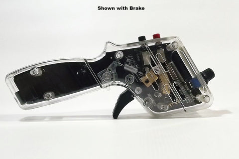
Wiper Finger Replacement or Cleaning:
Casing halve split:
- Remove the upper handle casings by removing the 3 M2x20mm screws and nuts that hold the two halves together. (Only 3 are needed)
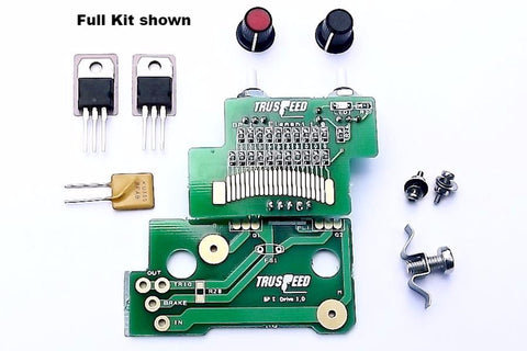
Element Contact Board removal:
- Remove the two M2 Nuts and washers holding the element board in place.
- If you have the Throw adjust fitted to your controller, unscrew the adjust screw almost all the way out. (This will allow the throw adjustment bracket to move with the element board when you unplug it.)
- Gently unplug the Element board taking care with the 3-way connector at the top right.
- The wiper fingers and the under side of the element contacts will now be exposed for inspection and cleaning.
Trigger removal:
- Remove the M2x6mm countersink screw and washer from the pivot centre on the trigger. It will now be free to slide off.
- Pop the end of the return spring out of the tensioner cam arm to allow free movement of the trigger when removed.
- Slip the trigger off the pivot and remove the other M2x8mm countersink screw and nut holding the wiper fingers to the trigger and slide the wiper fingers off the trigger. (Sometimes they are quite a tight fit over the round locating pin)
- Fit the new wiper fingers and re-assemble in the reverse order.
Re-assembly:
- Fit the trigger back in place but not the return spring yet.
- plug the element board back in but don't fit the nuts and washers yet.
- Check that there is a spring feel trying to push the element up when you press gently down with your fingers.
- Holding down the element with your fingers check that the wiper fingers move freely with just the tip touching the element.
- Now you can fit the washers and M2 nuts to secure the element.
- Re fit the trigger mounting screw and washer.
- Re-connect the return spring.
________________________________________
Trigger Loop Wire:
- For details on fitting this click the link for the .pdf download
- Link to the Facebook video click here