Customer Reviews
- The Dual Polarity option automatically senses the track wiring polarity so that your controller will work on both Positive and Negative wired tracks.
Negative Wired is typically Scalextric, Ninco and Carrera.
Positive Wired is typically club tracks. - The High Current option is only for positive wired tracks.
(These are typically the Positive Wired club tracks)
Current rating is not suitable for G12 motors or above with metal chassis racing - Comes with 1m Cable fitted to the controller.
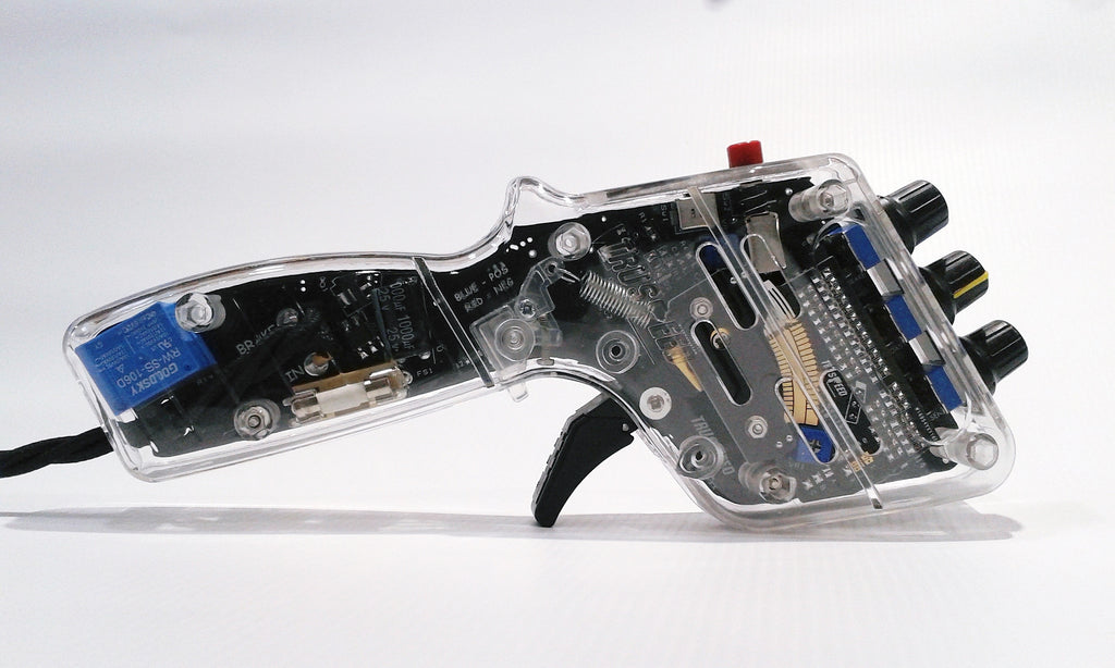
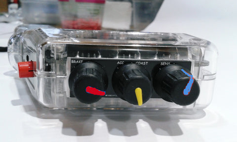
Simple intuitive controls on the MT II make it easy to use and quick to adapt to your racing style, car, and track conditions.
The High Current Positive is the most popular with 12A Peak and 6A running.
The Dual polarity automatically senses the track wiring but has lower current rating of 8A Peak and 3A Running.
Click on the links below under 'Spare Power Drive Boards' to read the details.
The Controller will be built using the optional components you add to the basket.
Everything will be ready to use. You just add the plug needed for your racing club.
-----------------------------------------------------------------------
Spare Power Drive Boards.
Details about the drive boards can be found in the links below.
- Dual Polarity (automatic sense of polarity) click here
- High Current Positive (positive wired tracks) click here
-----------------------------------------------------------------------
Optional extras:
- Throw adjust. click here
- UK Racing Plug (Choose fitted or separate) click here
-----------------------------------------------------------------------
(Review in Issue 4 of slotmagazine.co.uk)
- Dual Polarity Power Option (Current rating of 8A peak and 3A running)
- High Current Option (Current rating of 12A peak and 6A running)
(Suitable for motors below G12 for metal chassis racing) - Full Power Relay.
- Plug-in Replaceable Power Drive Board (see below)
- Supplied with the V.10 Contact Board with multiple mode options.
(Set to Negative Curve mode as standard since 2023).
(See details of options under Contact Board 10) - 36 step wiper element and 9 point contact Stainless Steel Wipers.
- PWM Drive and Brake Control.
- Switchable Power Coasting Feature allowing simulated Braking for cars that stop quickly even with no brakes applied.
- Brake adjustment.
- Launch Button.
- Acceleration Control.
- Sensitivity adjustment.
- Trigger return spring tension adjustment.
- User-Changeable Single and Double Finger Trigger.
- Fuse for over-current protection.
- LED (Power ON and goes off to show full power delivered to your car via the Relay)
- Shipping weight 325g.
Options: - Throw adjust. click here
- UK Racing Plug. click here
See the General Information Page for Start-up Settings. click here
Brake control:
(Turn Clockwise to increase Braking)
- Full braking is the same as a short circuit switch for very strong brakes.
- In NORMAL and COAST mode a single rotary control sets the brake strength from full to a gentle action.
- If the Brake control is turned all the way anti-clockwise for minimum brakes, but the car still stops too quickly (for example, a high magnet-force HO car, or car that slows rapidly even with no brakes), then the Coast mode can be selected. (Details in the next section)
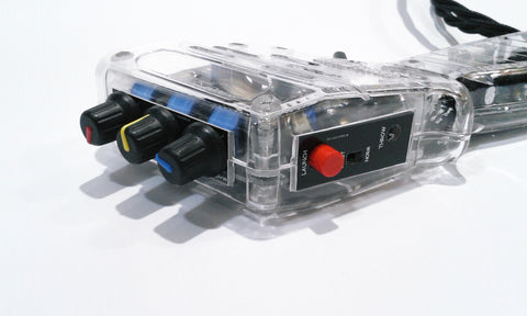
- The COAST and NORM select switch is located on the rear fascia under the LAUNCH button. (The switch is recessed so that it can't be accidentally switched during a race)
Acceleration and Coast Brake control:
(Turn Clockwise to increase acceleration in NORMAL MODE and to increase simulated Brakes in COAST MODE)
- In NORMAL mode this control sets the rate of acceleration. The idea is that even though the trigger may have been snatched quickly to full throttle, the controller will only feed power to the car at the rate set by this control. This prevents wasted time during wheel spinning and loss of traction as you exit a corner, or the guide lifting out of the slot with powerful motors.
- In COAST mode this control becomes a Brake Simulation adjustment suitable for those cars that stop almost immediately even with no brakes applied. The idea is that though the trigger has been released, the power fed to the motor decreases at a rate set by this control. Once the controller is no longer feeding power, the normal brakes will be applied at the rate you have set under BRAKE CONTROL as above. (For these cars the BRAKE will usually have be set to minimum)
Sensitivity control:
(Turn Clockwise to increase Sensitivity)
This adjusts the trigger wiper sensitivity to enable you to set the controller feel for any car or track condition. There is a built-in CURVE control circuit (similar to the PWM controller) which works automatically together with the sensitivity adjustment to give quick and easy settings. As the Sensitivity is turned up, so the initial start speed also rises slightly to match.
The little blue pre-set adjustment on the right hand side of the wiper element provides an adjustment for the range of the MODE function set on the contact board via the solder bridges.
For details on this see Contact Board 10.
If the THROW ADJUSTMENT option has been fitted, then, when the trigger is released for braking, it only goes back as far as your throw adjustment has been set, so the start speed can be made quite high with a combination of this adjustment and the sensitivity adjustment.
LAUNCH Switch:
-
While pressed IN, this switch cuts the feed to the car and motor, even if the trigger is pulled. Once released the power feeds in at whatever point the trigger has been pulled to, but at the rate set by the ACCELERATION control. The idea is that your trigger is already pulled in on the start line so that all you need to do is release the switch to give you a quicker start from the line.
- Another useful feature of the Launch Switch is that it will act as a coasting brake when pressed. If you have a section of track that doesn't really need as much braking as you have set, then you can press the switch to allow the car to coast under its own braking.
Trigger Return Spring Tension and Optional Throw Adjustments:
- Spring Tension: Under the Trigger is the adjustment Screw. It operates against a cam arm that pulls the return spring. Turn clockwise to increase tension and anti-clockwise to reduce it. (you can see it work through the clear handle)
- Throw Adjust: Through the access hole in the rear fascia is the throw adjustment screw. This sets the position that the trigger returns to when released for braking. Turn clockwise to move the stop point further in. (you will see the trigger move as you screw it in and out) The adjustment sets the amount of travel for the trigger by moving the position of the Brake contact. The further in you set it, the higher the start-up speed of the car, because, as the brake releases, the trigger is already some way across the element.
Power LED :
- LED Power Indicator. (BLUE for POSITIVE WIRED Track and RED for NEGATIVE WIRED Track.)
- The LED extinguishes when the relay energises and full power is delivered to the car
Wiring Colours:
- BROWN (WHITE) Power in. (Positive or Negative from Power Supply)
- BLUE (BLACK) Output. (Power from the controller to the track)
- GREEN (RED) Brake. (Negative or Positive from Power Supply)
Power and Current Ratings:
-
The Dual Polarity Board will handle motor stall currents of about 8A. (This is the high current used when the slot car is stationary and builds up to high speed in a short space of time.) The running current is rated at 3A.
This board does not handle as much current as the High Power Board because it has so many more components.
The Dual Polarity option automatically senses the track wiring polarity so that your controller will work on both Positive and Negative wired tracks.
There is a fuse in the power feed to the drive Mosfet that will cut the power if the average current use is too high for too long a period. -
High Current Board option is either Positive polarity only, and will handle 12A peak with 6A running current. For this option a T10A fuse is fitted.
It cannot be connected to a negatively wired track.
There is no change in performance or speed, it is just more rugged to handle higher current if required by the motor.
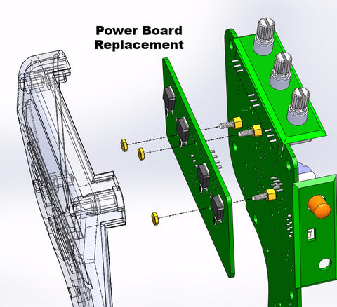
Plug-in Replacement Power Board: click for video
- Undo the handle casing screws and remove the casings. On the back of the main Board is the Power Drive Board.
- Undo the 3 M2 nuts using an M4 Nut wrench and unplug the Power Board. (it will slide over the threaded sections as the 4 pins unplug from the socket.)
- Plug in the replacement board (or the High Power Board option) and secure it again with the 3 M2 Nuts.
Additional images for this product show the power board both in place and removed, showing the nuts and driver.
Maintenance:
-
Once you feel a scratchy operation or can hear squeaking then it is advisable to apply a small amount of the lighter fluid, or something similar, onto a cotton bud and through the air flow slots in the casing, gently wipe over the contacts on the board.
- Be sure not to bend the cable at the exit of the handle. The wiring will break from metal fatigue after a while and cause intermittent operation. Wind the cable into a gentle coil and it will last.
- High Current Drive Board Replacement click here
Choose the polarity (most clubs use Positive wiring) - Dual Polarity Drive Board Replacement click here
- Drive P-Channel Mosfet click here
- Brake N-Channel Mosfet click here
- Sensitivity and Brake Pots B10K click here
Choose the style to match your model. - Replacement Cable click here
Choose the length and prepared ends - Trigger Sections click here
Choose the full kit or just plastic parts